Friday 10 July 2015

SQL SERVER Architecture - In depth Look - PART - II


SQL SERVER Architecture PART - I is covered here.

Memory Management

By default, SQL Server manages its memory resources almost completely dynamically. When allocating memory, SQL Server must communicate constantly with the operating system, which is one of the reasons the SQLOS layer of the engine is so important. 

Buffer is a page in memory that's the same size as data or index page. Buffer pool is the memory in which all frequently used data pages(data cache) are kept which are  read from disk and also the new insertion rows. Buffer manager is responsible for bringing the data to buffer pool from the disk whenever it requires. From SQL Server 2012 onward, all size of page allocations and CLR space allocation can be located inside the buffer pool itself.

Pages in the data cache are hashed for fast access. Hashing is a technique that uniformly maps a key via a hash function across a set of hash buckets. A hash table is a structure in memory that contains an array of pointers (implemented as a linked list) to the buffer pages. Every buffer in the data cache has a header that contains information about the last two times the page was referenced and some status information, including whether the page is dirty (has been changed since it was read in to disk). The reference information is used to implement the page replacement policy for the data cache pages, which uses an algorithm called LRU-K(Least Recently Used] in which K value of 2, so it keeps track of the two most recent accesses of each buffer page. An LRU-K algorithm keeps track of the last K times a page was referenced and can differentiate between types of pages, such as index and data pages, with different levels of frequency. 

Buffer pool memory that isn’t used for the data cache is used for other types of caches. The framework consists of set of stores and the Resource Monitor. There are three types of stores: 
  • Cache stores - Example. Procedure Cache.
  • User stores  - Example. Meta data cache.
  • Object stores - Example. SQLServer Network Interface(SNI) which leverages the object store for pooling network buffers.
Both cache stores and user stores use the same LRU mechanism and the same costing algorithm to determine which pages can stay and which can be freed. Object stores, on the other hand, are just pools of memory blocks and don’t require LRU or costing.

Lazy Writer examines the size of the free buffer list. If the list is below a certain threshold, which depends on the total size of the buffer pool, the lazy writer thread scans the buffer pool to repopulate the free list. As buffers are added to the free list, they are also written to disk if they are dirty. 

Checkpoint process scans the buffer cache periodically and writes any dirty data pages for a particular database to disk. The difference between the checkpoint process and the lazy writer (or the worker threads’ management of pages) is that the checkpoint process never puts buffers on the free list. The purpose of the checkpoint process is only to ensure that pages are written to disk, so that the number of dirty pages in memory is always kept to a minimum, which in turn ensures that the length of time SQL Server requires for recovery of a database after a failure is kept to a minimum.

Memory management in the stores takes into account both global and local memory management policies. Global policies consider the total memory on the system and enable the running of the clock algorithm across all the caches. Local policies involve looking at one store or cache in isolation and making sure it is not using a disproportionate amount of memory. To satisfy global and local policies, the SQL Server stores implement two hands: external and internal. Each store has two clock hands, and you can observe these by examining the DMV sys.dm_os_memory_cache_clock_hands. This view contains one internal and one external clock hand for each cache store or user store. The external clock hands implement the global policy, and the internal clock hands implement the local policy. The Resource Monitor is in charge of moving the external hands whenever it notices memory pressure.

Because memory is needed by so many components in SQL Server, and to make sure each component uses memory efficiently, Microsoft introduced a Memory Broker late in the development cycle for SQL Server 2008. The Memory Broker’s job is to analyze the behavior of SQL Server with respect to memory consumption and to improve dynamic memory distribution. The Memory Broker is a centralized mechanism that dynamically distributes memory between the buffer pool, the query executor, the query optimizer, and all the various caches, and it attempts to adapt its distribution algorithm for different types of workloads.

Main differences between SQL Server 2012 with older versions.


Also find below Memory manager responsibility difference between SQL Server 2012 with older versions.


SQL SERVER - Architecture - In depth look - PART - I


SQL Server architecture comprises below listed components.
  • External Protocols
  • Query processor
  • Storage Engine
  • Access methods
  • SQL OS

External Protocols

Net Libraries are part of Database engine at Server side and SQL Native Client at Client side. With the help of Net Libraries, Application API prepares TDS(Tabular Data Stream) packets for any requests(T-SQL, Programming constructs) and encapsulates as part of protocol and sends to SQL Server for processing. Now Server side Net libraries converts TDS packets to language which is understandable by Query processor(relational engine). The configuration parameter of the Client and the instance of SQL Server determine which protocol should be used. SQL Server can be configured to support multiple protocols simultaneously in order to process requests from different clients. Each client connects to SQL Server with a single protocol. 


Here are the list external protocols that can be used in SQL Server.


  • Shared Memory: Clients using the Shared Memory protocol can connect only to a SQL Server instance running on the same computer.
  • Named Pipes: A protocol developed for local area networks (LAN). A portion of memory is used by one process to pass information to another process, so that the output of one is the input of the other.
  • TCP/IP: It can communicate across interconnected networks of computers with diverse hardware architectures and operating systems. It includes standards for routing network traffic and offers advanced security features.
  • VIA: It works only with CISCO VIA hardware. It is decommissioned in the latest version of SQL Server.
  • TDS Endpoint: Connections are represented as TDS endpoint. SQL Server creates endpoint associated with any of external four protocols. If the protocol is enabled, then endpoint can be used by users.If the protocol is disabled, endpoint will not be active. Dedicated endpoint is created for Dedicated Administrator Connection(DAC) which can be used only by the member of sysadmin fixed server role.

Query processor [Relational Engine]

Query processor comprises below listed components.

Command Parser: It checks the syntax of queries/statements and translates into internal format which is called as Query tree.

Query Optimizer: It takes Query tree from Command parser and prepares it for optimization. As part of the preparation, it segregates and marks statements as it can be optimized or can not be optimized.Flow-of-control and DDL statements can not be optimized. DML Statements can be optimized. It optimizes statements which are marked for optimization, checks security and compiles into an internal form which is called as Execution plan. Statements marked for not to be optimized, directly process for compilation, security checks and  it becomes an execution plan.


SQL Manager: It is responsible for managing stored procedure and its re-compilation, caching of its plans, reusing plans in case of parameterized.

Database Manager: It responsible for handling access to the meta data during query compilation and optimization.

Query Execution: It acts like a dispatcher which simply executes each command from the execution plan.

Storage Engine

It comprises three components which are 
  • Access methods 
  • Transaction Management and 
  • Some components from SQL OS.
Communication between Query processor and Storage Engine would be OLE DB row sets.


Access Method:

Whenever query optimizer needs to perform READ\WRITE operation on storage Engine, then access Method code will be created. Suppose set of rows needs to be read from database, then access method calls buffer manager which internally serving the pages in its cache or reads it to cache from disk. Row and Index operations are part of access method components. 

The row operation code performs READ\WRITE operation on individual rows. If it needs to write some data, then access method code will be initiated, lock and transaction manager finds a row which is appropriately locked as part of transaction. After row is formatted in memory, access method(row operation) code inserts a row in memory. Index operation code supports and helps to search B-Tree(Balanced Tree) indexing structure in order to traverse through multiple branches to access the data.

Page allocation code helps to allocate the pages to the database. SQL Server uses below listed type of pages for data storage and allocation.
  • Data pages - All users data are stored at data pages.
  • LOB pages - All large size user's data that are text, image, or ntext or if the row is too large to fit on a single page.
  • Index Pages - Index table data are stored at Index pages.
  • PFS[Page Free Space] - It Keeps track of which pages in a database are available to hold new data.
  • GAM[Global Allocation Map] and SGAM [Secondary GAM] - Information about allocated Extents. GAM is for Uniform extents and SGAM is for mixed extents.
  • IAM [Index Allocation Map] - Information about extents used by table or Index.
  • BCM[Bulk Changed Map] - Information about extents modified by bulk operations since last LOG Backup.
  • DCM [Differential Change Map] - Information about extents that have changed since lost BACKUP Database.
Version Operations helps to maintain different row versions of same data during snapshot isolation and Online Index rebuild activities etc.

Transaction Management:

Transaction service is to establish the ACID properties. WAL(Write ahead Logging) helps to work towards roll back and roll forward operations.

Lock Manager: The locking code acquires and releases various types of locks, such as share locks for reading, exclusive locks for writing, intent locks taken at a higher granularity to signal a potential “plan” to perform some operation, and extent locks for space allocation. It manages compatibility between the lock types, resolves deadlocks, and escalates locks if needed. The locking code controls table, page, and row locks as well as system data locks. 

Lets see SQL Server memory management in the PART-II.

Wednesday 8 July 2015

SQL SERVER 2014 New Features - Always on Availability Groups Enhancement


Always on feature has been introduced at SQL Server 2012 which combines the power of Database Mirroring and Clustering. Like clustering, Always on also works on top of Windows clustering but without the need of Shared storage(SAN). It enables high availability and disaster recovery for multiple SQL Server databases.


  • In SQL 2012, we can have maximum of four secondary replicas for read, backup, HA and DR. Up to three of those secondary replicas can be synchronous. Any two of the sync replicas can perform automatic fail over. With SQL Server 2014, Always on supports up to eight secondary replicas. Also these secondary replicas has been enhanced to allow read workloads to continue to run even in case of primary is not available due to network failures or the loss of quorum for the windows server fail over cluster.
  • SQL Server 2014 Always on feature is closely integrated with Windows Azure in which we can create one or more asynchronous secondary replicas on Windows Azure Infrastructure as a Service(Iaas) services. Also we can configure Always on availability groups with synchronous secondary replica for SQL Server databases that are hosted in Windows Azure Iaas Services to provide automatic fail over in case of server or VM failure.
  • With SQL Server 2014 Always on availability groups, diagnostics and troubleshooting method has been enhanced to provide more specific information. Also included new columns as part of the Always on dashboard.

Tuesday 7 July 2015

Password-Less SSH in HADOOP CLUSTER


Distributed HADOOP cluster setup requires SSH key based authentication among master and slave nodes. Using SSH key based authentication, master node can connect to slave nodes or secondary nodes to start/stop the daemons\processes without any password. For example master node launches node manager and data node daemons in all the slave machines using SSH key based authentication. If password-less SSH is not setup, user has to manually specify the password on each individual machine to start all the processes.


Here are the steps to setup password-less ssh.

Step-1
Install SSH-Client on the master
>> sudo apt-get install openssh-client

Step-2
Install SSH-server on all the slave machines
>> sudo apt-get install openssh-server

Step-3
Generate the SSH key. We can generate DSA or RSA keys. Both are encryption algorithms.
>> ssh-keygen -t rsa

DSA means Digital Signature Algorithm
RSA means Rivest Shamir Adleman


Go to .ssh directory and list the files.
>> cd .ssh/
>> ls
Here we can find id_rsa.pub (public key) and id_rsa (private key) files.

Step-4
Copy the public key to all the slave machines.
>> ssh-copy-id -i id_rsa.pub username@slave-hostname

New file will be created as "authroized_keys" which has the same content as public key.

If the master node also acts as a slave machine, then copy the public key to local authorized keys as below:
>> cd .ssh
>> cat id_rsa.pub >> authorized_keys

Step-5
Verify the SSH connection as below. It should get connected without prompting the password.

>> ssh username@slave-hostname

Monday 6 July 2015

SQL Server 2014 New Features - Delayed Durability


Writing the transaction log records to the disk is required for a transaction to be durable. This is one of the ACID properties.

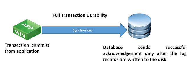
SQL Server transaction commit process can be fully durable or delayed durable(lazy commit). In fully durable, transaction is synchronous between application\client and database in which SQL Server sends successful acknowledgement only after the log records are written to the disk. 

In delayed durable, transaction is asynchronous in which SQL Server sends commits as successful before the log records are written to the disk. Transaction commit process does not wait for the log I/O to finish. Log records are kept in memory which will automatically flushes to disk once the log buffer fills (or) user can manually executes the system stored procedure sp_flush_log to flush the content to disk. As log records are flushed to disk once the log buffer fills by default, single instance of flushing capacity will be in larger chunk which reduces I/O contention and increases throughput during concurrent transactions.

We can set the transaction durability in database level or in {atomic block\Transaction\Commit} level.


Saturday 4 July 2015

SQL SERVER 2014 New Features - In-Memory OLTP Engine(Hekaton)


Microsoft introduced excellent new feature called In-Memory OLTP engine in which selected tables are entirely in memory for high performance and low-latency data access. Hekaton is the Greek word for "100" - representing Microsoft's goal of improving performance by 100x.

Key features in In-Memory OLTP Engine
  • It has lock-free design in which relation database engine's locks and latches will not be used. This is the main key differentiation point between In-Memory OLTP Engine and DBCC PINTABLE or putting databases on SSDs which are using the same relational engine with its locks and latches.
  • It uses new optimistic multi-version concurrency control mechanism. When a row in a memory(shared buffer) is modified, In-Memory OLTP engine creates entirely new version of that row with the timestamp. This process is very fast as it is done in memory.
  • As In-Memory OLTP engine maintains multiple versions of data, we will find lot of deleted\discarded rows in memory over a time. Microsoft implemented new lock-free garbage collection process in order to clean-up all these unwanted rows from memory in periodical basis.
  • It also uses the efficient stored procedure compilation process which takes interpreted T-SQL code and compiles it into native Win64 code.This is to reduce the CPU execution time while processing the query.
  • In-Memory OLTP table uses the HASH indexes (or) memory-optimized non-clustered indexes. It doesn't use the B-tree structures used by on-disk indexes.Hash indexes are best for item lookup and memory optimized non-clustered indexes are best for range of values. Memory-optimized tables can support only maximum of eight indexes.
  • Microsoft includes the new Analysis, Migrate and Report(AMR) tool to identify the tables and stored procedures that would benefit by moving them into memory. And also helping to perform the actual migration of those database objects.
  • In-Memory OLTP maintains less logging. All logging for memory-optimized tables are logical.
    • No log records for physical structure modifications.
    • No index-specific / index-maintenance log records.
    • No UNDO information is logged


Here is the script to create In-Memory OLTP Database

We can also use the SSMS to add the Memory Optimized File group by navigating to Database properties --> Filegroups


  •   Data files are ~128 MB in size and it writes 256 KB chunks at a time. It stores only the inserted rows.

  •   Delta file size is not constant and it writes 4 KB chunks at a time. It stores IDs of deleted rows.

Here is the script to create Memory optimized table.
There are two possible values for DURABILITY that are
  • SCHEMA_AND_DATA - both schema and data will be persisted
  • SCHEMA_ONLY - Only schema will be persisted and not data.

Find below the sample In-Memory OLTP stored procedure.

This stored procedure will be compiled into a native Win64 DLL that contains native processor instructions that are executed directly by the CPU, without the need for interpretation.

When we use the NATIVE_COMPILATION keyword, we must also include:
  • SCHEMABINDING: It indicates that tables referenced by this stored procedure can't be dropped. This keyword is only valid for natively compiled stored procedures in SQL Server 2014.
  • EXECUTE AS: This option controls the user context under which the stored procedure should be executed.
  • BEGIN ATOMIC: Natively compiled stored procedure body must consist of exactly one atomic block, which we specify with the BEGIN ATOMIC keywords. The atomic block requires that both the TRANSACTION ISOLATION LEVEL and LANGUAGE options be specified. In addition, any tables that are referenced must use a two-part naming scheme.

In-Memory OLTP Architecture 


Client application connects to TDS handler in order to access either disk based table or memory optimized table. Memory optimized table can be accessed by interpreted T-SQL through query interop utilities. And natively compiled stored procedure can access only memory optimized tables.

Friday 3 July 2015

MS SQL SERVER DBA - Course Content


LIVE ONLINE TRAINING COURSE CONTENT FOR MS SQL SERVER 2012 DBA AND 2014 NEW FEATURES.


TO ENROLL TO THIS COURSE CLICK HERE

Thursday 2 July 2015

Hive Web Interface(HWI) setup on Hadoop Cluster


HWI stands for Hive Web Interface. It is the web URL through which we can browse through all the objects (such as databases, tables etc..) in the Hive

In order to access HWI web URL, hive's HWI service needs to be started and running.

Here is the command to start HWI service.

>> $HIVE_HOME/bin/hive --service hwi

Once HWI Service is started, use the below URL to get into HWI Interface.


Hive's HWI feature is presently broken and is unsupported at CDH virtual boxes. Instead of that CDH provides Beeswax as a better Hive front end via HUE.

Tiny Information about HADOOP History


Here are the small information about Hadoop History.
  • In 2002, Doug Cutting created an open source, called web crawler project. 
  • In 2004, Google published Map Reduce, GFS papers. Google owns a DFS known as "Google File System (GFS)"  developed by Google Inc. for its own use.
  • In 2006, Doug Cutting developed the open source called Map reduce and HDFS project. 
  • In 2008, Yahoo ran 4,000 node Hadoop cluster and Hadoop won terabyte sort benchmark. Yahoo also developed PIG for non-java developers.
  • In 2009, Facebook launched SQL support for Hadoop which is called as HIVE. Facebook also developed FUSE(Filesystem in User Space)

RACK Awareness and Configuration in HADOOP Cluster


Rack is the collection of machines which are physically located in a single place\data-center connected through traditional network design and top of rack switching mechanism. In Hadoop, Rack is a physical collection of slave machines put together at a single location for data storage. There can be multiple racks in a single location.

When the client is ready to load a file into the cluster, the content of the file will be divided into blocks(each Block size 128 MB) and then client consults the Name node and gets the address of data nodes for the default 3 replication copies for every block. While placing in the data nodes, the key rule followed is "for every block of data, two copies will exist in one rack, third copy in the different rack". This rule is called as "Replica Placement Policy".

Rack topology is configured in hadoop by implementing a script that, when given a list of host names or IP addresses on the command line, prints the rack in which machine is location , in order. Topology scripts are used by hadoop to determine the rack location of nodes. This information is used by hadoop to replicate block data to redundant racks.

Here is the sample representation for Replication Rack awareness.


Here is the sample bash shell script.

HADOOP_CONF=/etc/hadoop/conf 

while [ $# -gt 0 ] ; do
  nodeArg=$1
  exec< ${HADOOP_CONF}/topology.data 
  result="" 
  while read line ; do
    ar=( $line ) 
    if [ "${ar[0]}" = "$nodeArg" ] ; then
      result="${ar[1]}"
    fi
  done 
  shift 
  if [ -z "$result" ] ; then
    echo -n "/default/rack "
  else
    echo -n "$result "
  fi
done 

Here is the topology data.

hadoopdata1.ec.com     /dc1/rack1
hadoopdata1               /dc1/rack1
10.1.1.1                     /dc1/rack2